Features: | |
---|---|
Availability: | |
Quantity: | |
TD3810
TUNKIA
1. Summary
TD3810 is a comprehensive testing system dedicated to the on-site assessment of the AC electricity meter verification device. The functional integration of the instrument is extremely high, and a set of equipment can complete the verification items specified by JJG 597 (insulation and voltage test require the cooperation of safety equipment). It is not only suitable for assessing the three-phase energy standard device, but also used as a high grade energy standard meter.
2. Features
• Power / power accuracy 0.01,0.02 optional.
• Voltage measurement range: 6 V ~528 V (customized for wider range).
• Current measurement range: 0.2 mA ~ 120 A.
• Basal wave frequency: 45 Hz ~65 Hz (optional 400Hz).
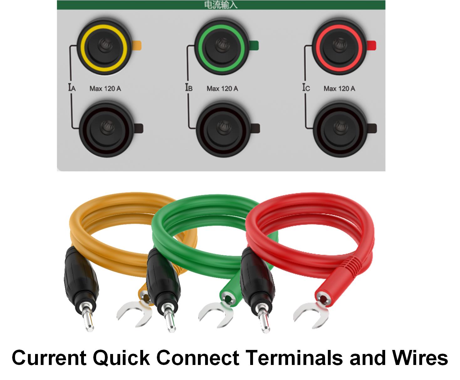
• The current is input by a pair of terminal posts without changing change.
• Phase measurement uncertainty up to 0.003° (class 0.01)
• Voltage and current support the fully automatic range shift.
• Both voltage and current support 2 to 127 harmonic measurements.
• It has the function of comprehensive statistical analysis of the measured electricity quantity.
• Support the graphical display of phor map, spectrum map and trend map.
• With the standard power pulse input / output function.
• In the limit state, the instrument is not damaged and the value is accurate.
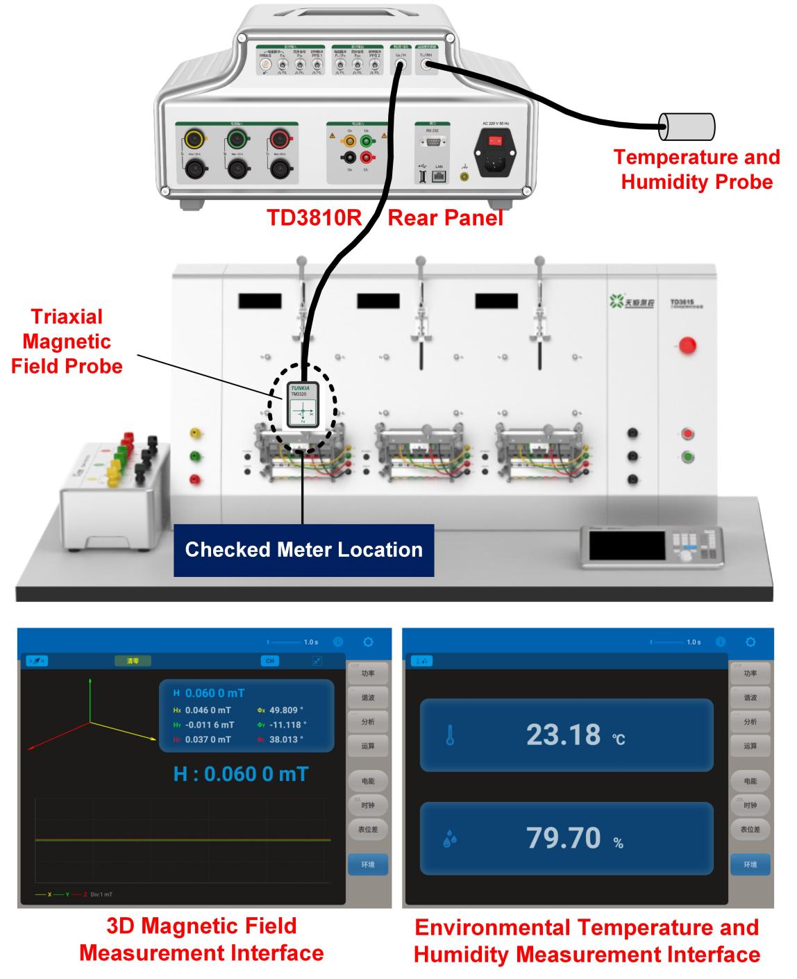
• Support for temperature and humidity, magnetic field, daily timing error and other measurement functions
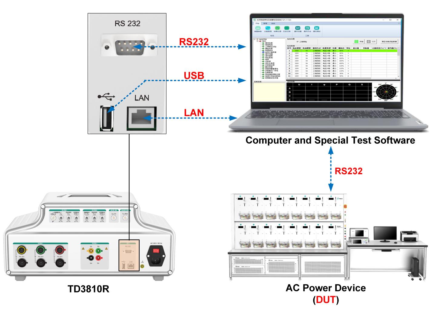
• Rich communication interfaces: USB, RS232, LAN.
• With a large size LCD touch touch screen.
3. Applications
☆ Assessment of Single-phase / Three-phase Energy Meter verification Device | ||||
• On-site assessment of single phase electric energy meter verification device and single phase standard electricity meter with class 0.02 and below meeting R46 instruction • The electric energy device can be assessed according to the JJG 597 regulations. The possible verification items are as follows: | ||||
Intrinsic Error | Power Stability | Interrelationship | The Influence of Alternating Alternating Magnetic Field | Multiplex Output Consistency |
Adjustable Range | Measurement Repeatability | Degree of Symmetry | Potential Difference between the Terminals of the Same Name | Short-term Stability Variation |
Fineness Adjustment | The Magnetic Field of the Device | Phase Sequence | Monitoring Indication Error | Variation Within Calibration Cycle |
Load Effect | Waveform Distortion |
☆ Calibrate Single-phase / Three-phase Power Source / Meter |
• Suitable for calibrating single / three-phase power standard source and power meter of Class 0.02 and below (with stable power source). |
4. Characteristics
☆ Front Panel of the Instrument | |
S/N | Function |
Built handle, that is, does not occupy space and convenient for users to carry instruments. | |
10.4-inch LCD touch color screen, multi-power intuitive display, full touch screen operation, more convenient operation. | |
The folding foot can raise the instrument by about 15° for optimal operation and reading view. |
☆ Rear Panel of the Instrument | |
S/N | Function |
Three-phase current fast connection terminal: the primary wiring can achieve a wide range of 0.2 mA ~120 A current measurement. | |
Three-phase voltage terminal: primary wiring can achieve voltage measurement of 6 V ~528 V. | |
Rich communication interface: including RS232, USB, LAN, easy for users to set up an automatic test system. | |
Shell ground: Make that the casing ground is reliably grounded before use. | |
Power interface: AC 220V power input interface with switch and safety pipe. | |
Pulse input terminal: from left to right, photoelectric pulse, electric energy pulse, synchronous signal and clock pulse PPS. | |
Pulse output terminal: from left to right is the electric energy pulse FL/ FH, Synchronous signal, clock pulse PPS 2. | |
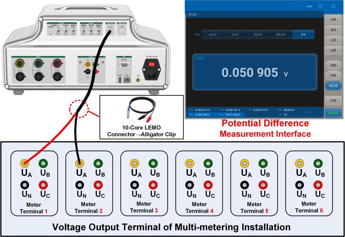
Epitope difference / magnetic field measurement: it is used to measure the magnetic field in the 3 D magnetic field sensor; in the epitope difference sensor, it can measure the potential difference between the same phase voltage terminals of the multi-epitope device. | |
Temperature and humidity measurement: the temperature and humidity sensor is used to measure the temperature and humidity of the site. |
5. Functional characteristics
☆ Wide Range of Current Measurement |
|
☆ High Reliability of the Instrument |
• There is complete electrical isolation between the voltage and current measurement circuits; in the limit state (500 V, 100 A), it will not damage the instrument, and can ensure the accurate value. |
☆ Easy to Use On-site | |
The main weight of the instrument is 9.9 kg and equipped with a special pull rod instrument box, which can put the host, test wire and laptop computer in it, and the transportation is very convenient. The notebook is equipped with special software meeting the requirements of JJG 597, which can automatically complete the error analysis, data recording, export or printing certificate of the device on site. |
☆ Comprehensive Analysis of AC Power | |
S/N | Function |
The measuring channel has the function of oscilloscope, which can display the waveform of the measured power in real time. | |
Accurately measure the phase between the voltage and current of each phase, and show it intuitively in the form of the phasor diagram. | |
Calculate the harmonic distortion of THD / T (harmonic relative to full wave) and THD / F (harmonic relative to base wave). | |
The amplitude (RMS), content (%) and phase of the second ~ 127th harmonic of each phase voltage or current can be analyzed in real time, and the base wave measurement frequency is 45 Hz~65 Hz or 45 Hz~400 Hz optional; It is used to check whether the harmonic content and phase of the complex waveform output by the R46 device meet the requirements of the procedure. | |
Show the frequency spectrum of each harmonic directly in the form of a bar chart (100%). |
☆ Harmonic Power / Electric Power Measurement | |
S/N | Function |
Can choose full wave, base wave, single harmonic, harmonic section to measure power, electric energy. | |
It can be measured according to active power, reactive power and apparent power. | |
Harmonic section can be set to measure power or electric energy. |
☆ Data Statistical Analysis Function | |
S/N | Function |
Statistical analysis of data: calculate the maximum (Max), minimum (Min), peak-peak (P-P), the mean (Avg), the standard variance (S.dev) class. | |
Power stability test: during the test cycle, draw the curve of power change over time in real time. | |
Normal distribution histogram: displays the distribution of the counted power quantity during the test period. | |
Power stability test: the output power stability of the inspected electric energy device can be automatically calculated according to the algorithm of JJG 597-2005 "Verification Regulations for AC Electricity Meter Verification Device". |
☆ The “Potential Difference Between the Same Name Buttons” of the Measuring Device |
• Built-in small signal AC voltmeter, can measure the "potential difference between the same name buttons" of the device. • The input terminal can continuously withstand a voltage of 250 V to prevent misaccess to 220V, and the high voltage causes damage to the internal voltmeter. |
☆ The "Daily Timing Error" of the Measurement Device |
• Built-in standard second pulse input / output function, annual measurement uncertainty (k=2): 510-8 • The daily timing error of the device can be assessed. |
☆ Measure the "Magnetic Field of the Device" and the Environment |
• The built-in 3 D magnetic intensity meter for measuring weak magnetic signals has better performance than the ordinary one; the triaxial probe is not required to find the maximum magnetic field, which greatly improves the detection efficiency. • The built-in environmental temperature and humidity measurement function can reduce the number of equipment carried by users to the site, and also save the initial investment. |
☆ Rich Communication Interface and Special Test Software |
• The rear panel of the instrument is equipped with RS232, USB, LAN and other rich communication interfaces, to facilitate the establishment of automatic test system. |
6. Technical Specifications
6.1 Three-phase Voltage Measurement
Range | Resolving Power | Measurement Uncertainty (k = 2) ( ppm*RD + ppm*RG )[1] | Temperature Coefficient @ (15~30) °C (ppm*RD+ppm *RG ) /°C | ||
Class 0.02 | Class 0.01 | Class 0.02 | Class 0.01 | ||
60 V | 10 μV | 60 + 40 | 30 + 20 | 0.5 + 0.5 | 0.25 + 0.25 |
120 V | 0.1mV | 60 + 40 | 30 + 20 | 0.5 + 0.5 | 0.25 + 0.25 |
240 V | 0.1mV | 60 + 40 | 30 + 20 | 0.5 + 0.5 | 0.25 + 0.25 |
480 V | 0.1mV | 60 + 40 | 30 + 20 | 0.5 + 0.5 | 0.25 + 0.25 |
Note {1]: RD is the read value and RG is the range value, the same below. |
• Measurement range: 6 V ~528 V (wider range supports customization), 7-bit display, manual / automatic range shift
6.2 Three-phase Current Measurement
Class 0.01 Specification | |||||
Range | Resolving Power | Measurement Uncertainty at different frequencies (Hz) (k = 2) ( ppm*RD + ppm*RG ) | Temperature Coefficient @ (15~30) °C (ppm*RD+ppm *RG) /°C | ||
45 ≤ F ≤ 65 | 65 < F ≤ 200 | 200 < F ≤ 400 | |||
5 mA | 1 nA | 120 + 80 | 240 + 160 | 480 + 320 | 5 + 5 |
10 mA | 10 nA | 60 + 40 | 120 + 80 | 240 + 160 | 3 + 3 |
20 mA | 10 nA | 60 + 40 | 120 + 80 | 240 + 160 | 0.75 + 0.75 |
50 mA | 10 nA | 30 + 20 | 60 + 40 | 120 + 80 | 0.25 + 0.25 |
100 mA | 0.1 μA | 30 + 20 | 60 + 40 | 120 + 80 | 0.25 + 0.25 |
200 mA | 0.1 μA | 30 + 20 | 60 + 40 | 120 + 80 | 0.25 + 0.25 |
500 mA | 0.1 μA | 30 + 20 | 60 + 40 | 120 + 80 | 0.25 + 0.25 |
1 A | 1 μA | 30 + 20 | 60 + 40 | 120 + 80 | 0.25 + 0.25 |
2 A | 1 μA | 30 + 20 | 60 + 40 | 120 + 80 | 0.25 + 0.25 |
5 A | 1 μA | 30 + 20 | 60 + 40 | 120 + 80 | 0.25 + 0.25 |
10 A | 10 μA | 30 + 20 | 60 + 40 | 120 + 80 | 0.25 + 0.25 |
20 A | 10 μA | 30 + 20 | 60 + 40 | 120 + 80 | 0.25 + 0.25 |
50 A | 10 μA | 30 + 20 | 60 + 40 | 120 + 80 | 0.25 + 0.25 |
100 A | 100 μA | 30 + 20 | 60 + 40 | 120 + 80 | 0.25 + 0.25 |
• Measurement range: 0.2 mA ~ 120 A, 7-bit display, manual / automatic range shift
Class 0.02 Specification | |||||
Range | Resolving Power | Measurement Uncertainty at different frequencies (Hz) (k = 2) ( ppm*RD + ppm*RG ) | Temperature Coefficient @ (15~30)°C (ppm*RD+ppm *RG) /°C | ||
45 ≤ F ≤ 65 | 65 < F ≤ 200 | 200 < F ≤ 400 | |||
5 mA | 1 nA | 240 + 160 | 480 + 320 | 1000 + 600 | 10 + 10 |
10 mA | 10 nA | 120 + 80 | 240 + 160 | 480 + 320 | 5 + 5 |
20 mA | 10 nA | 120 + 80 | 240 + 160 | 480 + 320 | 1.25 + 1.25 |
50 mA | 10 nA | 60 + 40 | 120 + 80 | 240 + 160 | 0.5 + 0.5 |
100 mA | 0.1 μA | 60 + 40 | 120 + 80 | 240 + 160 | 0.5 + 0.5 |
200 mA | 0.1 μA | 60 + 40 | 120 + 80 | 240 + 160 | 0.5 + 0.5 |
500 mA | 0.1 μA | 60 + 40 | 120 + 80 | 240 + 160 | 0.5 + 0.5 |
1 A | 1 μA | 60 + 40 | 120 + 80 | 240 + 160 | 0.5 + 0.5 |
2 A | 1 μA | 60 + 40 | 120 + 80 | 240 + 160 | 0.5 + 0.5 |
5 A | 1 μA | 60 + 40 | 120 + 80 | 240 + 160 | 0.5 + 0.5 |
10 A | 10 μA | 60 + 40 | 120 + 80 | 240 + 160 | 0.5 + 0.5 |
20 A | 10 μA | 60 + 40 | 120 + 80 | 240 + 160 | 0.5 + 0.5 |
50 A | 10 μA | 60 + 40 | 120 + 80 | 240 + 160 | 0.5 + 0.5 |
100 A | 100 μA | 60 + 40 | 120 + 80 | 240 + 160 | 0.5 + 0.5 |
• Measurement range: 0.2 mA ~ 120 A, 7-bit display, manual / automatic range shift
6.3 Frequency / Phase Measurement
Class 0.01 Specification | ||||
Type of Measurement | TD3810 | TD3810-R | ||
Frequency | measuring range | 45 Hz ~65 Hz | 45 Hz ~400 Hz | |
Minimum resolution | 0.000 01 Hz | 0.000 01 Hz | ||
Measurement uncertainty (k=2) | 0.005%*RD | 0.005%*RD | ||
Phase Position | measuring range | 0~360°(I ≥ 50mA ) | 0~360°(I ≥ 50mA ) | |
Minimum resolution | 0.000 1° | 0.000 1° | ||
Measurement uncertainty (k=2) | 45 Hz ≤ F ≤ 65 Hz | 0.003° | 0.003° | |
65 Hz < F ≤ 200 Hz | —— | 0.01° | ||
200 Hz < F ≤ 400 Hz | —— | 0.02° | ||
Class 0.02 Specification | ||||
Type of Measurement | TD3810 | TD3810-R | ||
Frequency | measuring range | 45 Hz ~65 Hz | 45 Hz ~400 Hz | |
Minimum resolution | 0.000 01 Hz | 0.000 01 Hz | ||
Measurement uncertainty (k=2) | 0.005%*RD | 0.005%*RD | ||
Phase Position | measuring range | 0~360°(I ≥ 50mA ) | 0~360°(I ≥ 50mA ) | |
Minimum resolution | 0.000 1° | 0.000 1° | ||
Measurement uncertainty (k=2) | 45 Hz ≤ F ≤ 65 Hz | 0.006° | 0.006° | |
65 Hz < F ≤ 200 Hz | —— | 0.02° | ||
200 Hz < F ≤ 400 Hz | —— | 0.04° |
6.4 Power / Electric Energy Measurement
Class 0.02 Specification | |||||
Voltage Range | Current range | Power Factor | Measurement Uncertainty at different frequencies (Hz) (k=2) | ||
45 ≤ F ≤ 65 | 65 < F ≤ 200 | 200 < F ≤ 400 | |||
30 V ≤ U ≤ 480 V | 50 mA ≤ I ≤120 A | 0.5L~1~0.5C | 0.01%*RD | 0.02%*RD | 0.04%*RD |
10 mA ≤ I < 50 mA | 1 | 0.01%*RD | 0.03%*RD | 0.08%*RD | |
0.5L~1~0.5C | 0.02%*RD | ||||
3 mA ≤ I < 10 mA | 1 | 0.02%*RD | - | - | |
0.5L~1~0.5C | 0.04%*RD | - | - | ||
0.2 mA ≤ I < 3 mA | 1 | 0.02%*RD×3mA/I | - | - | |
Class 0.05 Specification | |||||
Voltage Range | Current Range | Power Factor | Measurement Uncertainty at different frequencies (Hz) (k=2) | ||
45 ≤ F ≤ 65 | 65 < F ≤ 200 | 200 < F ≤ 400 | |||
30 V ≤ U ≤ 480 V | 50 mA ≤ I ≤120 A | 0.5L~1~0.5C | 0.02%*RD | 0.04%*RD | 0.08%*RD |
10 mA ≤ I < 50 mA | 1 | 0.02%*RD | 0.06%*RD | 0.16%*RD | |
0.5L~1~0.5C | 0.04%*RD | ||||
3 mA ≤ I < 10 mA | 1 | 0.04%*RD | - | - | |
0.5L~1~0.5C | 0.08%*RD | - | - | ||
0.2 mA ≤ I < 3 mA | 1 | 0.04%*RD×3mA/I | - | - |
• Power / electric power measurement range: the combination of AC voltage range and AC flow range
• Power factor measurement range: -1.000 000... 0.000 000... 1.000 000
• Standard electric energy pulse output: high frequency full range value corresponds to 60 kHz, low frequency full range value corresponds to 6 Hz
• Standard electric energy pulse input: frequency 200 kHz, voltage: 0... 3 V... 24 V
6.5 Other Measurement Functions
Device Magnetic Field Measurement | Range | 100 μ T, 1 mT, and 5 bits are shown |
Measurement Uncertainty (k=2) | 0.5% | |
Probe | Three-dimensional magnetic field sensing probe | |
Remarks | To measure the position of the measuring meter of the electric energy meter verification device | |
Object Difference Measurement | Range | 5 mV , 50 mV, 500 mV, 5V |
Measurement Uncertainty (k=2) | 0.2 mV | |
Remarks | Can to withstand 250 V | |
Clock Measurement | Function | PPS standard second pulse output, measurement |
Measurement Uncertainty (k=2) | 5×10⁻⁸ |
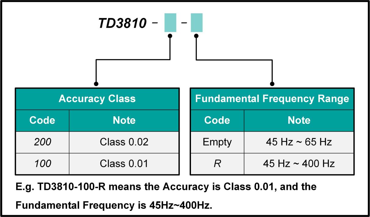
7. Ordering Information
8. General Technical Specifications
Power Supply Voltage | AC ( 220 ± 22 ) V, ( 50 ± 2 ) Hz |
Maximum Power Dissipation | 80 VA |
Preheating Time | 30 Minutes |
Temperature Performance | Operating temperature: 5°C~45°C Storage temperature: -10°C~55°C |
Humidity Performance | Working Humidity: <80% @ 30°C, <70% @ 40°C, and <40% @ 50°C Storage humidity: (20%~80%) R·H, no condensation |
Altitude | < 3000 m |
Instrument Quality | About 9.9 kg |
Communication Interface | RS232, USB , LAN |
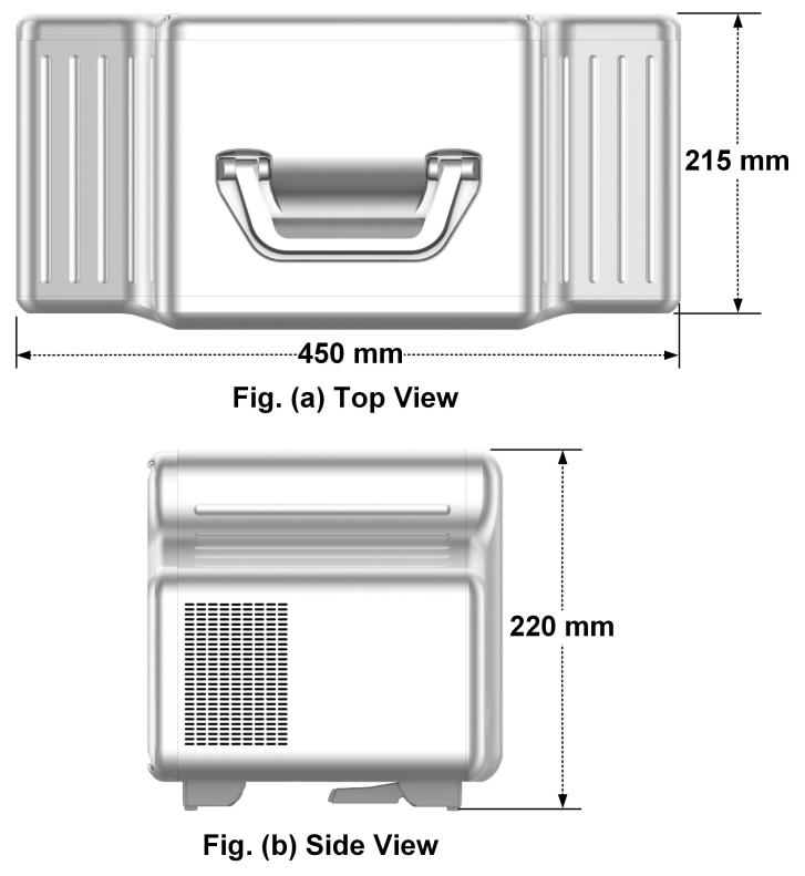
Dimension | 450 mm (W) ×215 mm (D) ×220 mm (H) (excluding handle) |
9. List of accessories
S/N | Picture | Name | Specifications | Quantity | Remarks |
1 | Voltage combination test wires | 3m/1.6mm2/ Φ 4- Φ 4 gun | Yellow, green, red and black Each 1 root | Standard accessories | |
2 | 10A Current test | 3m/2.1mm2/ Φ 4- Φ 4 gun | One for each root, yellow, green and red Black 3 root | Standard accessories | |
3 | Current snap plug test wire | 1.5m/25mm2/ Φ 12 insert MC quick plug test cable | One for each root, yellow, green and red Black 3 root | Standard accessories | |
4 | Electric energy pulse signal line | 1.5 m / BNC male head-crocodile clip two lines | One root | Standard accessories | |
5 | Signal test wire | 1.5 m / BNC head-BNC head | One root | Standard accessories | |
6 | Three-axis magnetic field sensing probe | —— | One root | Standard accessories | |
7 | Epitope difference, test line | 10 core, rammo head crocodile clip | One root | Standard accessories | |
8 | Temperature and humidity sensing probe | —— | One | Standard accessories | |
9 | Card U disk | Contains special test software | A set | Standard accessories | |
10 | Line from USB to RS232 | 1.8m / DB9 parent seat | One root | Standard accessories | |
11 | Diameter reduction plug | MC patchplug | Red 6 | Standard accessories | |
12 | power line | AC 220V, 10A | One root | Standard accessories | |
13 | Glass fuse | F3A , 250V | Three | Standard accessories | |
14 | Portable instrument box | Waterproof, seismic and anti-static resistance | One | Standard accessories |