- Home
- Products
- Advanced Multiproduct / Multifunction Calibrator
- TH1950 High Precision Multi-function Calibrator
- TD1880 Precision Multi-function Calibrator
- TD1870 Multi-function Calibrator
- TD1860 Multi-function Calibrator
- TD1855 Multi-function Calibrator
- TD1858 Portable Multi-function Calibrator
- TD1850 Multi-function Calibrator
- TD1500 High-precision DC Standard Source
- TD1020 Current Coil
- TD1000 Clamp Meters Calibration Device
- TD1050 Clamp Meters calibration device
- EV Charger Tester and Loads
- TK4830 Portable Tester for AC DC EV Chargers
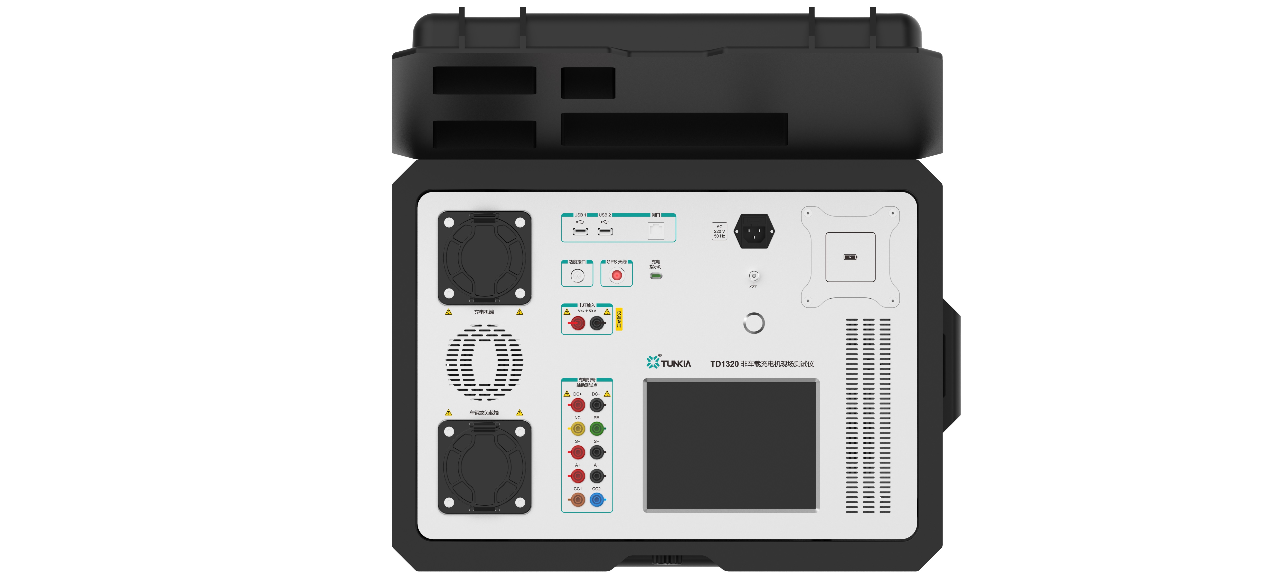
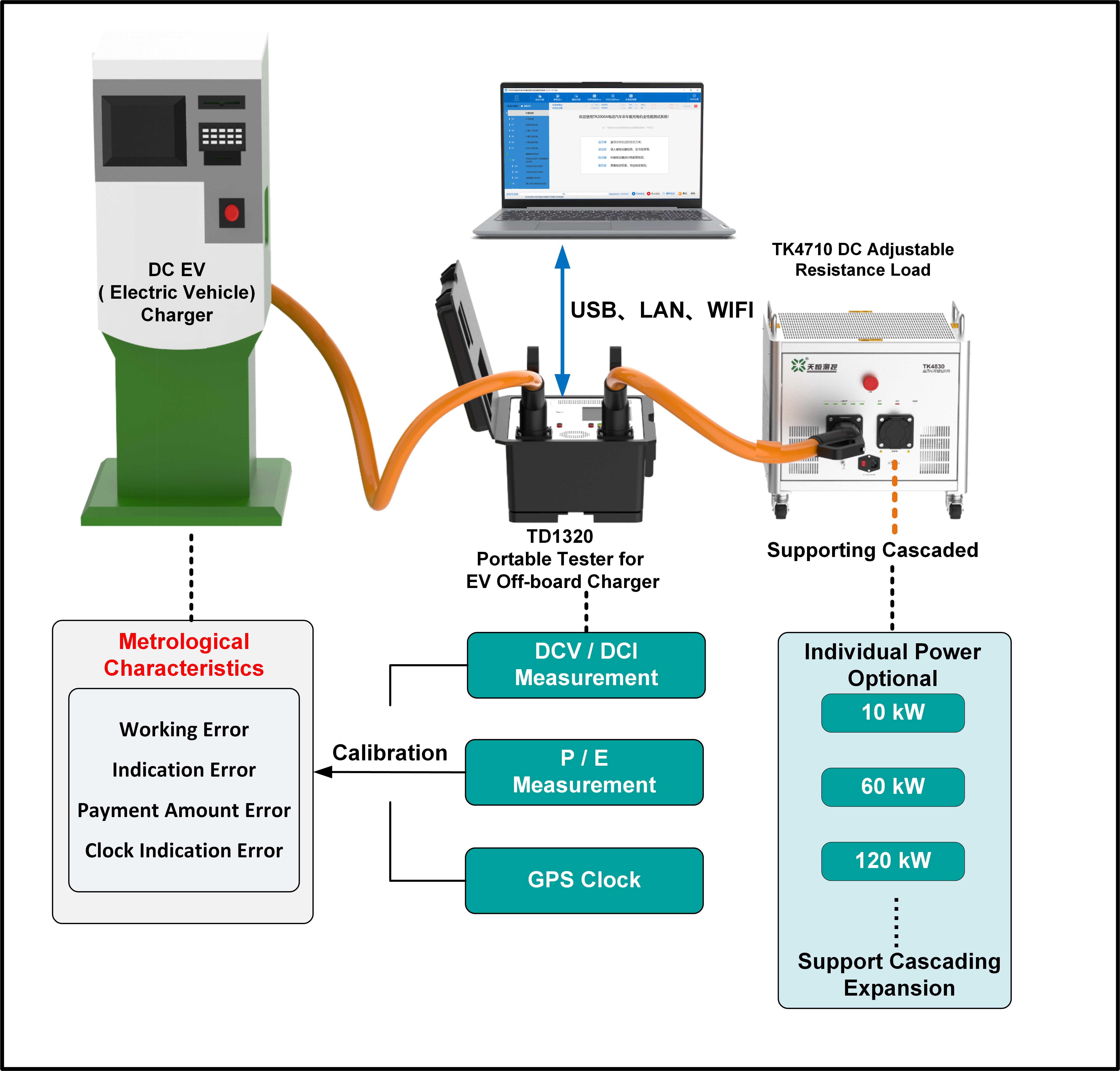
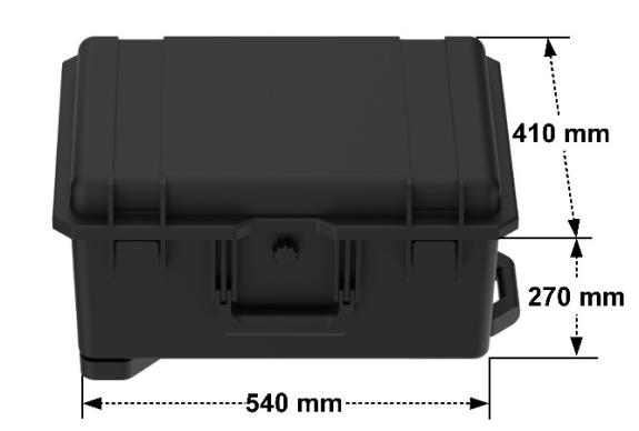
- TD1320 Portable Tester for DC EV Chargers
- TD1330 Portable Tester for AC EV Chargers
- TK4850E DC EV Charging Station Testing Device
- TK4860E AC EV Charging Station Testing Device
- TK4800 Calibration Device for Portable Tester for EV Chargers
- TK4710 DC Adjustable Resistance Load
- TK4720 AC Adjustable Resistance Load
- TK4730 AC/DC Portable Resistive Load
- TK4830Z Portable Tester for DC EV Chargers
- TK4960 DC Charging-power Calibration Adapter
- TK4965 AC Charging-power Calibration Adapter
- Advanced Electrical Reference Standards
- TH0100/TH0104 Advanced DC Voltage Reference Standard
- TH0110 Programmable DC Voltage Reference Standard
- TH0150 Wideband Voltage Divider
- TH0170 Precision DC High Voltage Divider
- TH0180 Precision AC/DC High Voltage Divider
- TH0190 Handheld Precision Voltmeter
- TH0195 AC/DC Voltage Measuring Standard
- TH0400 Precision Coaxial Current Shunt
- TH0410 High Frequency Coaxial Shunt
- TH0420 Reference Coaxial Current Shunt
- TH0460 Coaxial Shunt Multiplexing Unit
- TH0470 Precision Wideband Buffer
- TH0475 High Frequency Voltage Isolation Buffer
- TH0480 Resistance Time Constant Standard
- TH0490 Bisector Current Ratio Standard
- TH0500 Precision Current Transformer
- TH0540 Precision Current Transducer
- TH0600 Precision AC Current Transformer
- TH0680 Multiplexing I/V Selection Units
- TH0690 Current Transducer Integrated Measurement Analyzer
- TH0780 Multiplexing V/V Selection Units
- TH1000 Ultra-stable Precision Current Source
- TH1200 Nanovoltmeters Calibrator
- TH2000 Vector Voltage Analyzer
- Electrical Resistance Standard
- TH0200 Standard Resistance Measuring Device
- TH0210 Standard Resistance Measuring Device
- TH0240 Standard Resistance Multiplexer
- TH0260 Precision Resistance Analyzer
- TH0300 High Power Resistance Standard
- TH0310 Resistance Standard
- TH0320 Reference Resistance Standard
- TH0330 Ultra-Stable Resistance Standard
- TH0340 AC Resistance Standard
- TH0350 DC Bridges Calibrator
- TH0360 High-precision DC Resistance Meter Calibrator
- TD1400 Loop Resistance Tester
- TD1450 Analog Standard Resistor
- TD1470 Single and Double Arm Bridge Calibration Device
- TD1540 DC Shunt Verification Device
- TD2100 DC Shunt Verification Device
- AC DC Current Source and Meter
- TH0520 Precision Current & Voltage Measurement Standard
- TH0530 Precision Through-core Ammeter
- TH0630 Precision Through-core AC Ammeter
- TA1000 Transconductance Current Standard Source
- TD1090 Through-core AC I/V Transformer
- TA1200 High Frequency Transconductance Amplifier
- TH1300 DC High Current Sensor & Shunt Calibration System
- TA1300 AC Current Standard Source
- TA1500 AC/DC Current Standard Source
- TD2010 DC High Current Standard Source
- TA1100 Transconductance Amplifier
- DC Power/Energy Standards
- TH3000 AC/ DC Power & Energy Measurement Standard
- TH3900 DC Power & Energy Reference Standard
- TD1300 Precision DC Standard Meter
- TD1310 Precision AC/DC Standard Meter
- TD1545 DC Energy Meters Verification Device
- TD1548 DC Energy Meter Comprehensive Verification Device
- TD1550 DC Energy Meters Verification Device
- TD1570 Indirect Connected DC Energy Meters Verification Device
- TD1575 DC Energy Meters Verification Device
- TD1580 DC Energy Meters Testing Device
- Wideband Power Source/Meter
- Single-phase/Three-phase Standard Meter
- TK3300 Installed Three-Phase Standard Energy Meter
- TD3310 Three-phase Multi-function Standard Meter
- TD3110 Single-Phase Multi-Function Standard Meter
- TK3100 Installed Single-Phase Standard Energy Meter
- TD3300 Three Phase Multi-function Standard Meter
- TD3100 Single-phase Multi-function Standard Meter
- TD3810 Three-phase Energy Device Field Testing System
- TD3250 Portable Three-phase Energy Meter Tester
- Single-phase/Three-phase Energy Meter standard Calibration Device
- TH3600 Broadband Low Current Standard Power Source
- TD3500 Single-phase Energy Meters Verification Device
- TD3750 AC Power Detection Device for Electromagnetic Compatibility Testing
- TD3600 Three-phase Energy Meters Verification Device
- TD3650 Three-phase Energy Meters Verification Device
- TD3610 Three-phase Standard Energy Meters Verification Device
- TD3760 Complex Waveform Testing Device
- TD3900 High-precision Three-phase Power Source
- TD4550 Portable Tester for Three-phase Energy Meter
- TD4100 Portable Tester for Three-phase and DC Meters
- TD4200 Testing Device for Three-phase and DC Meters
- TD4500 PortableTester for AC Sampling Devices and Transmitters
- TD4510 Portable Tester for Three-phase and DC Meters
- TD4520 Portable Tester for Three-phase and DC Meters
- TD3550 Single-phase Energy Meters Verification Device
- TD4530 Portable Tester for Three-phase and DC Meters
- TD3700 Energy Meter Power Frequency Magnetic Field Test Device
- TD3710 Energy Meter Constant Magnetic Field Test Device
- TD3720 Load Current Rapid Change Test Device
- TD3730 Energy Meter Power Frequency Strong Magnetic Field Test Device
- TD3740 Energy Meter Durability Test Device
- Safety Instrument Detection
- TD1220 Verification Device for DC High Voltage & High Value Resistor
- TD1230 Verification Device for Withstanding Voltage Tester
- TD1240 Verification Load Bank for Withstanding Voltage Testers
- TD1250 Verification Device for Earth Continuity Testers
- TD1210 Verification Device for Leakage Current Tester
- High Voltage Standard Instrument
- TD2650 Precision AC/DC High Voltage Meter
- TD5400 High Voltage Wideband Electric Energy Measurement Test Device
- TD5560 Three-Phase High Voltage Wideband Power Standard Device
- TD5610 Three-Phase High Voltage Wideband Power Standard Meter
- TD2400 AC High Voltage Standard Source
- TD2410 High Voltage Meters Calibration Device
- TD2500 DC High Voltage Standard Source
- TD2550 Non-touch Static Voltmeters Calibration Device
- TD2600 Precision DC High Voltage Meter
- Industrial Instrument Testing
- TD7500 Process Signal Calibrator
- TD7600 Precision Process Calibrator
- TI1000 Precision AC/DC Voltage Calibrator
- TI1100 Precision AC/DC Current Calibrator
- TI1200 Precision DC Resistance Calibrator
- TI2000 DC High Current Standard Source
- TI2100 High-stable DC High Current Standard Source
- TI5000 DC Current Sensor Testing Device
- TI5100 DC High Voltage Sensor Testing Device
- TI5300 AC DC Current Sensor Testing Device
- TI5800 Sensor Power Supply and Output Tester
- TK2600 Pulse Voltage Source
- TK2650 Pulse Current Source
- TK6500 Electric Welding Machine AC/DC Power Calibrator
- TK6700 Electric Welding Machine Electric Power Parameters Comprehensive Calibrat
- TK6400 Load Box for Electric Welding Machine Calibration
- TP1000 Surface Resistance Tester
- TP2000 Handheld Temperature Humidity Meter
- TD6600 Relay Protection Tester Verification Device
- TK6800 Transformer Comprehensive Characteristic Tester Calibration Device
- TK8100 Calibrator for Low-voltage Circuit Breakers
- TD1170 Zinc Oxide Lightning Arrester Tester Calibration Device
- TD2700 Multi-Function Time Calibrator
- Calibrator for ESU Analyzer and Defibrillator Analyzer
- Magnetic Parameters Measurement and Calibration
- TM6140B Precision Magnetometer
- TM7600 Digital Integration Flux Meter
- TM7900 Precision Volt-second Generator For Flux Meter Calibration
- TM9000 Calibration System for Magnetometers
- TM9100 Precision Magnetometer Calibration Device
- TM9200 Alternating Magnetometer Calibration Device
- TM9300 Fluxgate Magnetometer Calibration Device
- TM5100 Handheld Tesla Meter
- TM5100A Handheld AC Magnetometer
- TM5120B Handheld Tesla Meter
- TM5340B Handheld Triaxial Tesla Meter
- TM6100 Gauss Meter
- TM6160B AC/DC Tesla Meter
- TM4100B Handheld Fluxgate Magnetometer
- TM4300B Handheld Triaxial Fluxgate Magnetometer
- TM4830B Fluxgate Magnetometer
- TM7100 Handheld Flux Meter
- TM7500 Flux Meter
- TH8010 Electrical Steel Magnetic Measurement Device Calibration System
- TH8020 Soft Magnetic Material DC Magnetic Meter Calibration System
- TH8030 Calibration System for Permanent Magnet Magnetic Measuring Instrument
- TH8100 Magnetic Field Coil Comprehensive Calibration Device
- TM1100/1110/1130 Hall Probe
- TM1200/1230 Fluxgate Probe
- TM2000/2030 Precision Current Source
- TM2300/TM2330 Helmholtz Coil
- TM2400 Solenoid
- Magnetic Material Testing Equipment
- TD81Series AC Magnetic Properties Measuring System for Soft Magnetic Materials
- TD8160 Magnetic Properties Measuring System for Single Sheet Amorphous
- TK8600 Metal Magnetic Powder Core Magnetic Properties Testing Device
- TS4000 DC Magnetic Properties Measuring System for Soft Magnetic Materials
- TS7710 Type A / B Permeameter
- TS7750 Solenoid
- TS7900 Multi-channel Permeability Meter Selector
- TS7910 Wiring Converter for Electrical Steel Magnetic Measuring Instrument
- TY1000 Magnetic Properties Measuring System for Hard Magnetic Materials
- TY1100 Magnetic Properties Measuring System for Hard Magnetic Materials
- TY1500 Electromagnet
- TY1550 Pole of Electromagnet
- TY1700 Search Coils
- TY1900 Specimen Heating Device
- TY2000 Surface Magnetic Field Automatic Testing System
- TY2100 Surface Magnetic Field Automatic Testing System
- TY2200 Surface Magnetic Distribution Automatic Testing Device
- TY2500 Multi-Probe Surface Magnetic Distribution Test Device
- TY3000 Magnetic Moment Tester
- TY3100 High-precision Magnetic Moment Tester
- TY3300 Magnetic Declination Tester
- TY3500 Pipe Inner Wall Oxide Scale Tester
- TY4810 Magnetic Moment Measurement Coil
- Electrical Steel Testing Equipment
- TD9100 Online Testing System for Magnetic Properties of Silicon Strip
- TS1000 DC Magnetic Properties Measuring System for Electrical Steel
- TS1020 DC Magnetic Properties Measuring System for Yoke Steel
- TS1100 AC Magnetic Properties Measuring System for Electrical Steel
- TS1200 AC Magnetic Properties Measuring System for Electrical Steel
- TS1300 AC/DC Magnetic Properties Measuring System for Electrical Steel
- TS2000 Rotational Magnetic Properties Measuring System for Electrical Steel
- TS2500 Magnetic Properties Measuring System for Electrical Steel Cores
- TS2600 Iron loss Fast Tester for Electrical Steel Sheets
- TS3000 Magnetic Properties Multifunction Measuring System for Electrical Steel
- TS3200 Electrical Steel Sheet Magnetic Properties Automatic Measurement System
- TS3210 Automatic Measurement System for Magnetic Properties of Electrical Steel
- TS1700 Surface Insulation Resistance Measuring System for Electrical Steel
- TS1710 Surface Insulation Resistance Automatic Measuring System for Electrical
- TS1780 Stacking Factor Measuring System for Electrical Steel Sheets
- TS1800 Bending Testing System for Electrical Steel Sheets
- TS1810 Bending Automatic Testing System for Electrical Steel Sheets
- TS7000/TS7010/TS7020/TS7100 Epstein Frame
- TS7500/TS7510 Single Sheet Tester
- TS1770 Silicon Steel Sheet Coating Adhesion Tester
- TS3300 Electrical Steel Magnetostriction Measurement Device
- Advanced Multiproduct / Multifunction Calibrator
- News
- Solution
- Multimeter Calibration
- High-Precision Multimeter Traceability
- Clamp Meter Calibration and Traceability
- Resistance Calibration
- Shunt Calibration
- Power Analyzer Calibration
- Three-Phase Power/Energy Calibration
- Sensor Testing
- EV Charger Tester
- Magnetic Material Testing
- Magnetometer Calibration
- Electrical Steel Testing
- Download
- About Us
- Contact Us
- All
- Product Name
- Product Keyword
- Product Model
- Product Summary
- Product Description
- Multi Field Search


